UNDERGROUND CUTTING TOOLS · APPLICATION & SUPPLY

Underground cutting tools
Selection. Spares. Supply.

Selection and supply support for disc cutters, scrapers, rippers and spares used in hard-rock TBMs, shield tunnelling, pipe jacking and microtunnelling. Review ground, cutter positions and mounting drawings before agreeing configuration and delivery.

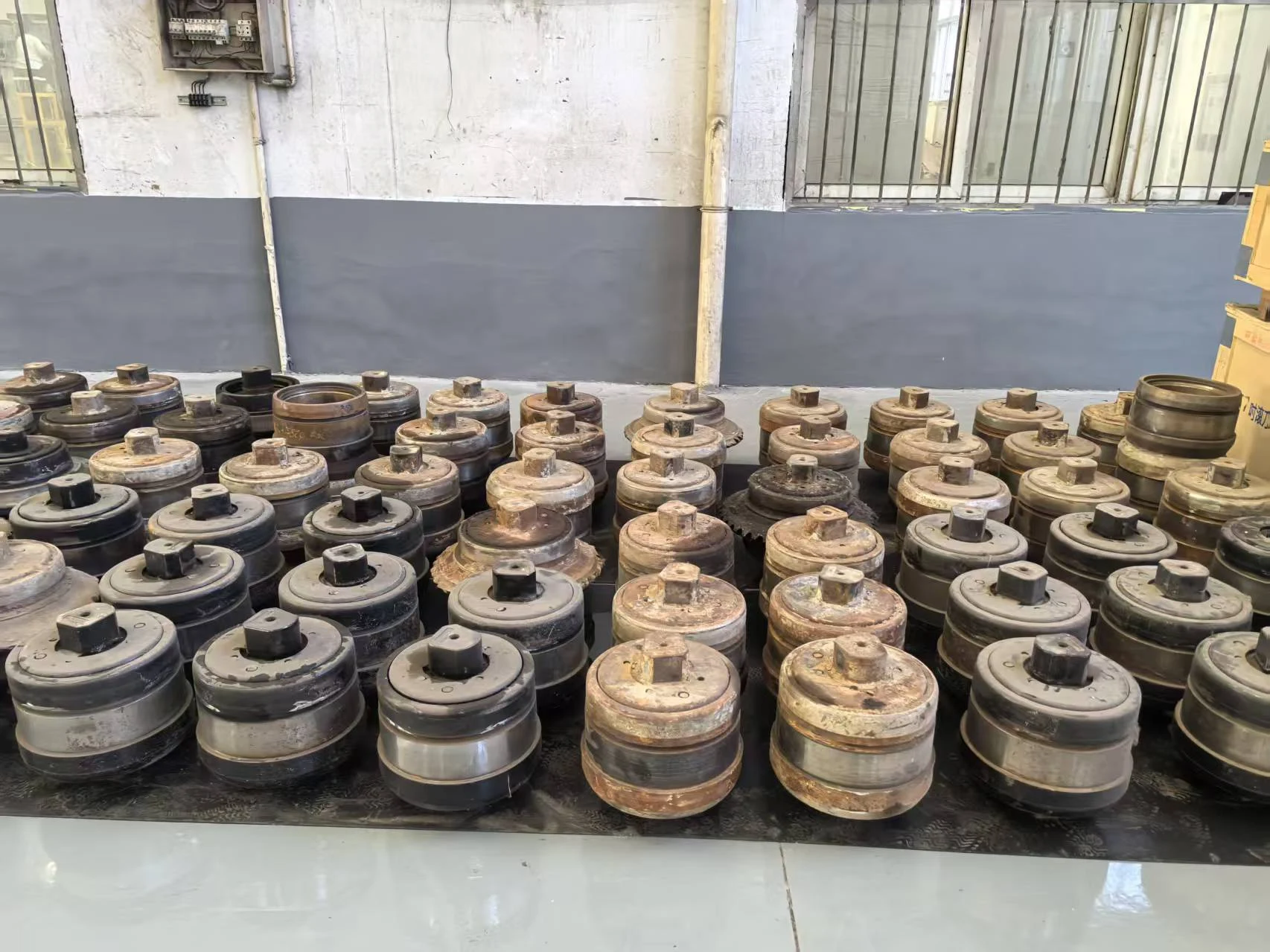
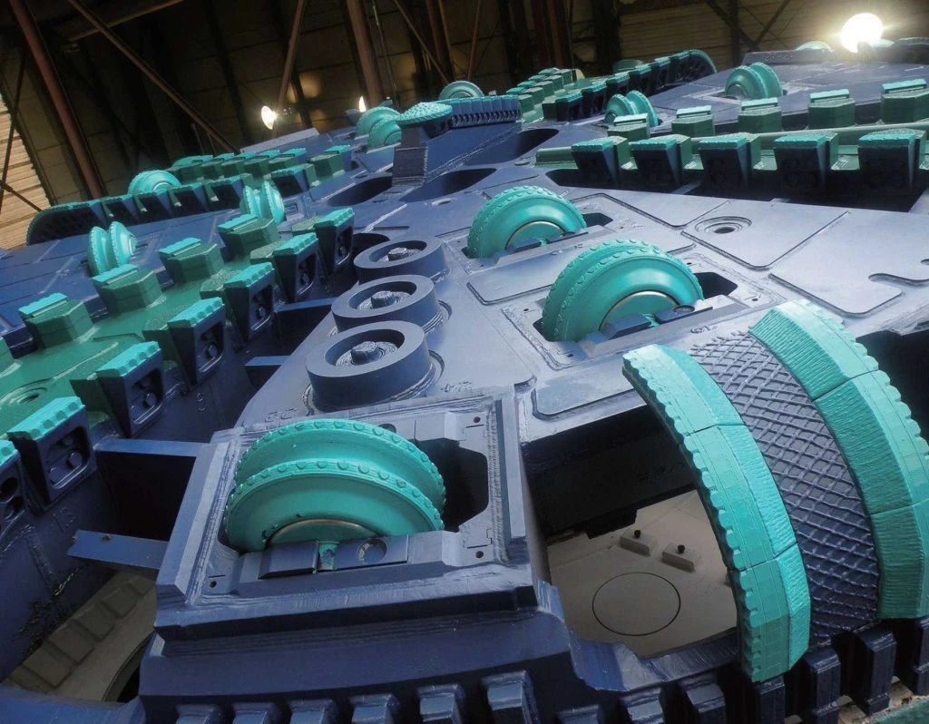
滚刀产品陈列 / Disc cutter stock
Disc cutter assemblies and sparesGround compatibility · Interface checks · Spares & maintenance
Hard-rock TBMsRock breaking & cutter configuration
Shield tunnellingSoft & mixed-ground cutting
Pipe jacking & MTBMCompact cutterheads & access
Spares & wear partsDrawings, traceability & delivery

Disc cutters, cutting tools and spares

A range of rock-breaking, cutting and wear components. Verify dimensions, materials, load capacity and pressure ratings against project information and approved drawings.

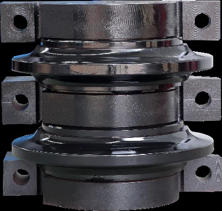
单刃滚刀 / Single-disc cutter
Hard-rock excavation

Single-disc cutter

Breaks rock by rolling indentation. Match cutter position, mounting dimensions and allowable load.

Ring
Outer diameter and tip width
Load
Allowable cutter load
Interface
Shaft ends and clamping dimensions
Position
Mounting angle and projection
Enquire about this tool ↗
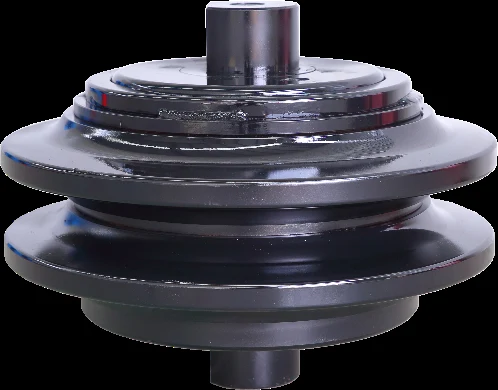
双刃滚刀 / Double-disc cutter
Two-ring assembly

Double-disc cutter

Paired cutter rings for specified positions. Confirm spacing, shaft arrangement and mounting orientation against drawings.

Assembly
Ring and shaft arrangement
Spacing
Ring centre-to-centre distance
Mounting
Housing clearance and orientation
Load
Allowable assembly load
Enquire about this tool ↗
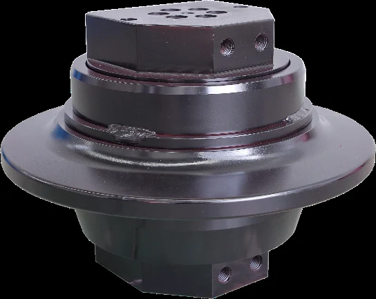
高水压滚刀 / High-pressure disc cutter
Pressurised conditions

High-pressure disc cutter

Check external water pressure, seal ratings and lubrication requirements. Confirm any pressure-compensation mechanism from the product drawing.

Pressure
Working pressure and variations
Sealing
Seal rating and test records
Compensation
Presence and mechanism type
Lubrication
Lubricant and servicing requirements
Enquire about this tool ↗
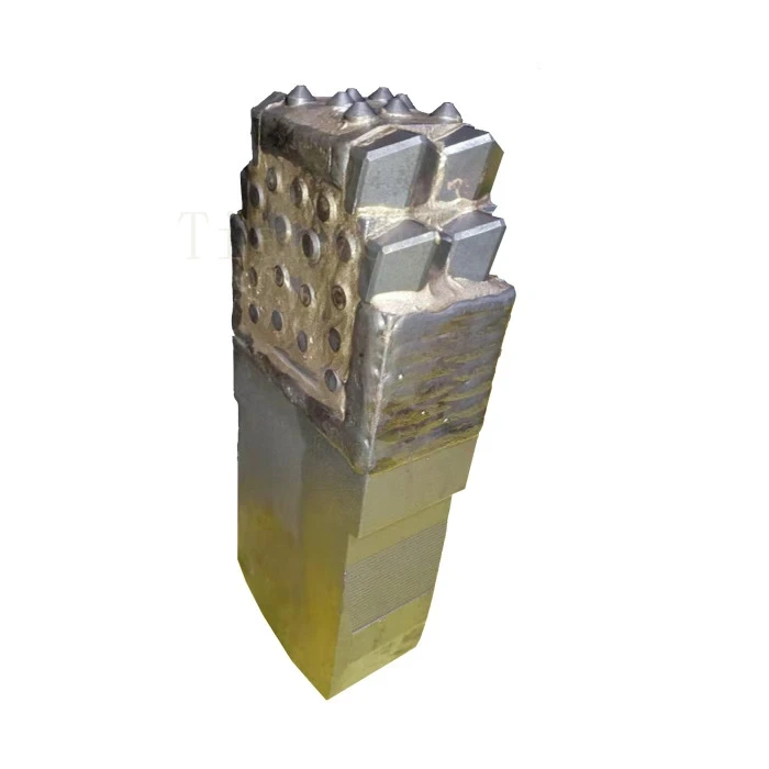
盾构撕裂刀实物 / Shield TBM ripper
Soft and mixed ground

Ripper

Penetrates and loosens ground and assists break-up. Check tool projection, carbide layout and holder interfaces.

Projection
Projection from cutterhead
Carbide
Grade and arrangement
Holder
Interface and attachment
Duty
Ground and impact conditions
Enquire about this tool ↗
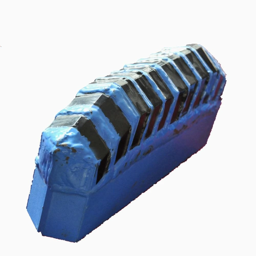
盾构边刮刀实物 / Shield TBM gauge scraper
Face and perimeter positions

Face and gauge scrapers

Face and gauge scrapers differ by mounting position. Check cutting direction, projection, carbide and steel body for each.

Position
Face or perimeter location
Direction
Rotation and cutting-face orientation
Dimensions
Cutting-edge dimensions and projection
Construction
Carbide and steel body
Enquire about this tool ↗
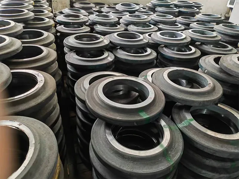
滚刀刀圈 / Disc cutter rings
Maintenance and spares

Disc cutter rings

The ring contacts the rock and wears in service. Verify its bore, outer diameter, tip width and fit to the cutter body against the drawing.

Profile
Outer diameter, tip width and profile
Fit
Bore and fit tolerance
Material
Steel grade and heat treatment
Traceability
Heat/batch ID and inspection records
Enquire about this component
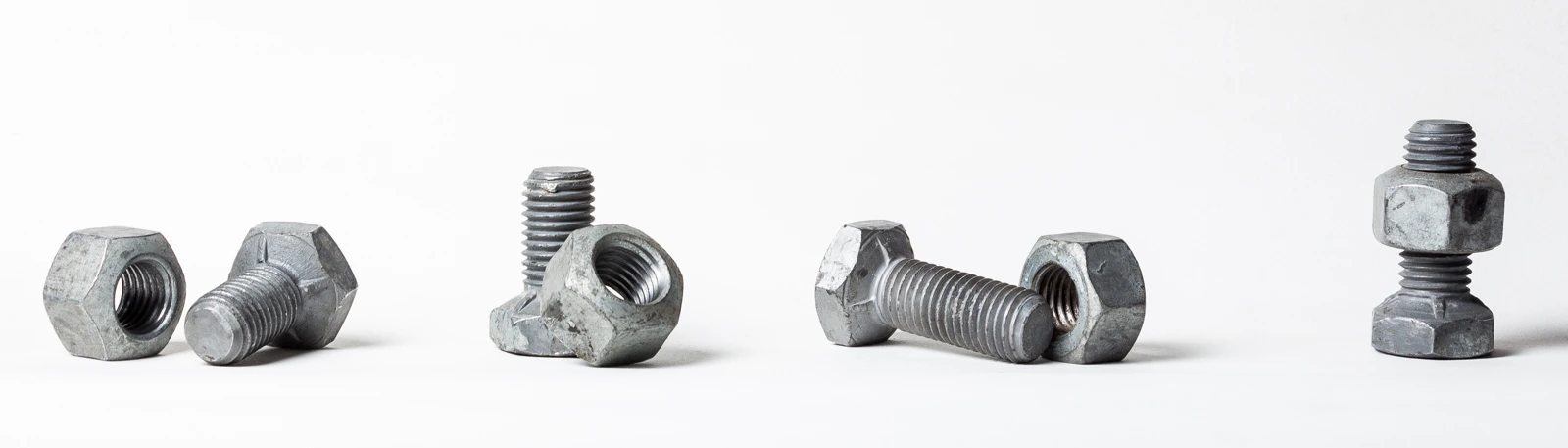
安装紧固件 / Mounting fasteners
Maintenance and spares

Mounting fasteners

Match bolts, nuts and washers to mounting drawings. Verify dimensions, property class, finish and the specified tightening method.

Thread
Diameter, pitch and effective length
Class
Bolt and nut property classes
Finish
Coating and environmental suitability
Tightening
Specified preload and tightening method
Enquire about this component
刀盘耐磨保护件 / Cutterhead wear protection
Maintenance and spares

Cutterhead wear protection

Wear liners and protection blocks reduce wear on cutterhead structures. Check material, thickness, attachment and replacement clearance for each protected area.

Location
Protected-area drawing
Material
Wear material and substrate compatibility
Dimensions
Thickness and replacement clearance
Attachment
Welded or mechanical attachment requirements
Enquire about this component

Product appearance identifies the family; supplied configuration, performance and interchangeability follow the agreed technical documentation.

How does a disc cutter fracture rock?

The cutterhead carries each cutter across the face, while contact drives rotation about its own shaft. Thrust is concentrated through the ring to produce crushing, cracks and chips.

24-second explainer · 1080p · Chinese / English subtitles · Engineering schematic, not a simulation

01

Local indentation

Normal force concentrates at the cutter edge, forming a local crushed zone.

02

Crack propagation

Continued rolling and successive loading of adjacent tracks extend cracks into the rock and towards neighbouring grooves.

03

Chip formation

Connected cracks allow rock chips to detach between tracks. Cutter spacing and penetration must be considered together.

Technical reference: Frontiers in Earth Science (2023), disc-cutter rock-breaking study ↗

From the cutter to the cutterhead

Explore cutter construction and cutterhead arrangements in documented photographs. Select an image to view it in high resolution.

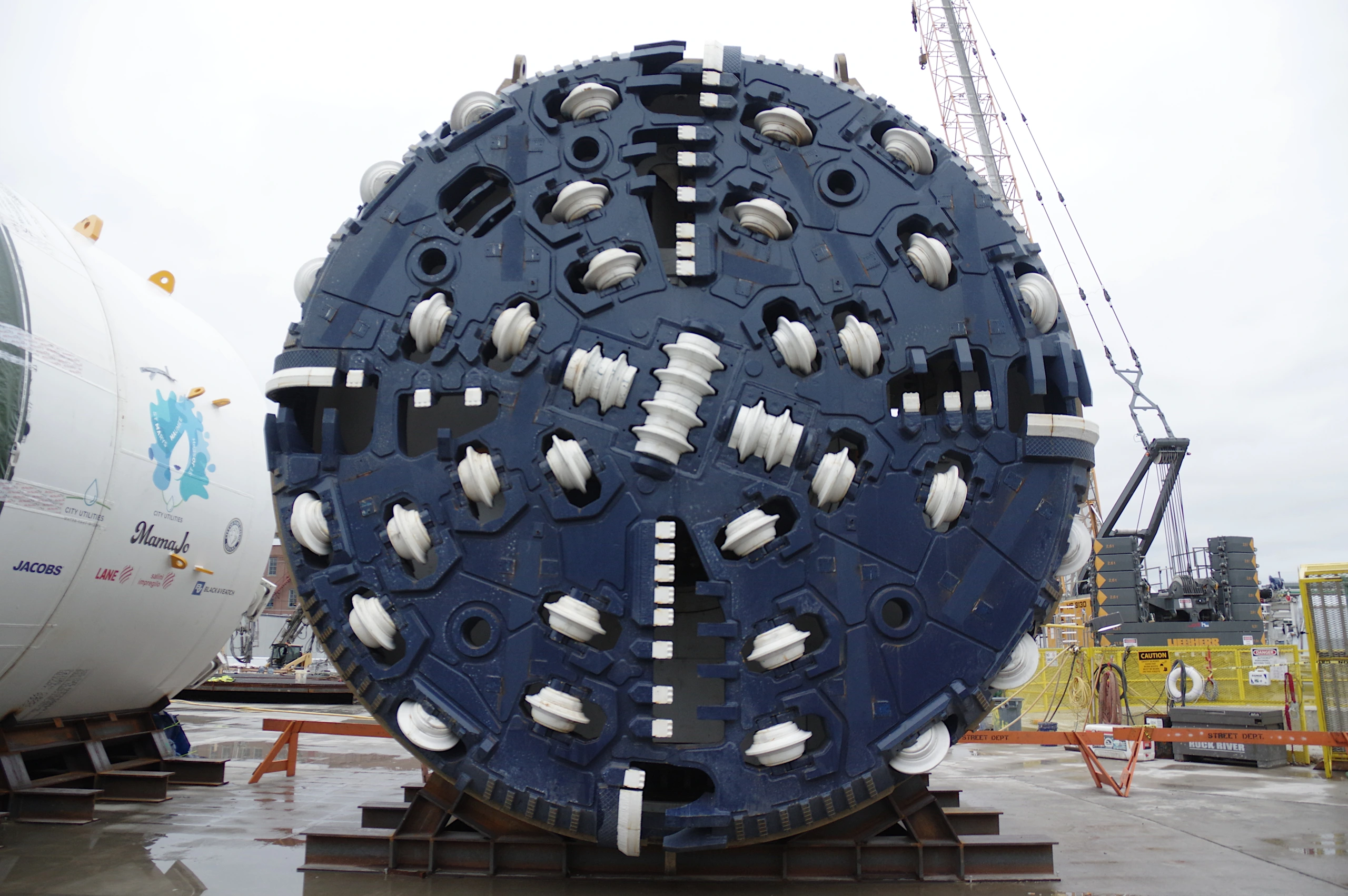
MamaJo TBM cutterhead with installed disc cutters, Fort Wayne, 2018

MamaJo TBM: an actual cutterhead with disc cutters

Fort Wayne, Indiana, USA, 2018. Disc cutters occupy different radial positions, with distinct arrangements and mounting orientations at the centre and perimeter.

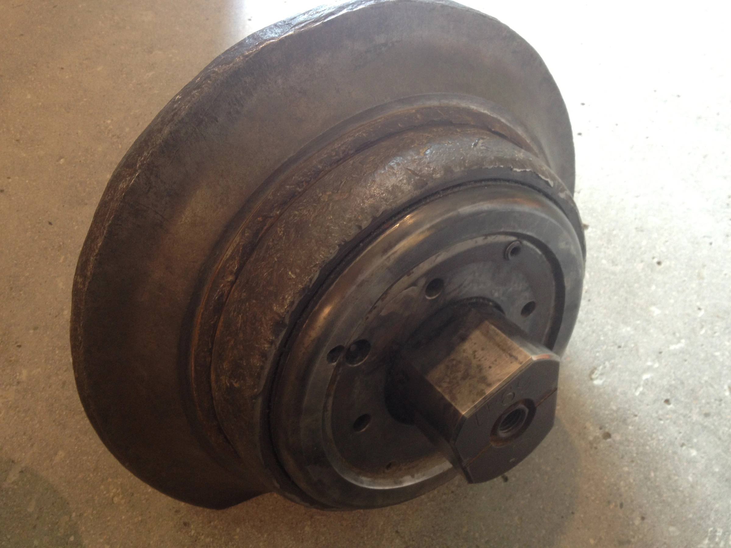
Disc cutter from Hallandsås tunnel TBM Åsa, photographed at Förslöv exhibition in 2013

Hallandsås tunnel: a disc cutter from TBM Åsa

Photographed at the tunnel exhibition in Förslöv, Sweden, in 2013. The component photograph shows the ring and assembly, complementing the cutterhead view.

Official videos open on the source website; availability depends on your network. The explainer above plays directly on this site.

Cutter selection and maintenance

Find guidance on rock breaking, mounting interfaces, wear records and procurement acceptance, organised around engineering questions.

Fundamentals

How does a disc cutter break rock?

Read guide

Thrust presses the cutter ring into the rock as the cutterhead rotates. Cracks develop beneath adjacent tracks and can connect to release chips. Rock strength, joints, cutter spacing and penetration jointly influence excavation.

Engineering checkpoint

Review spacing, penetration and chip characteristics rather than judging performance from rotational speed alone.

Useful project inputs

  • Cutter spacing and penetration per revolution
  • Chip characteristics and ground log

Interpretation limit: Fine muck alone does not establish cutter-ring wear as the cause.

Add to enquiry draft ↗
Fundamentals

Disc cutter, scraper or ripper?

Read guide

Disc cutters primarily break rock by rolling indentation. Scrapers cut soft or loosened material; rippers penetrate and loosen ground. Mixed-ground cutterheads may combine tool types according to the machine design.

Engineering checkpoint

Identify the ground and cutter-position function before confirming the tool designation and supply drawing.

Useful project inputs

  • Cutterhead layout and position functions
  • Current tool photographs and drawings

Interpretation limit: Similar names do not establish the same cutting action or interface.

Add to enquiry draft ↗
Selection

Why is UCS alone insufficient?

Read guide

Uniaxial compressive strength (UCS) describes intact-rock compressive strength, not abrasivity or rock-mass integrity. Review abrasivity tests, mineralogy, joint spacing, groundwater and mixed-face conditions, with sample representativeness.

Engineering checkpoint

Provide the geotechnical report, sampling locations and test methods; avoid comparing unlike measurements.

Useful project inputs

  • Intact-rock UCS test report
  • Abrasivity and joint survey data

Interpretation limit: Strength and abrasivity must be assessed separately.

Add to enquiry draft ↗
Selection

Is a larger cutter-ring diameter always better?

Read guide

Larger cutters require compatible mounting space, structure and drive capacity. Diameter must be considered alongside machine thrust, individual cutter load, spacing and cutterhead geometry. Replacement selection also requires projection and clearance checks.

Engineering checkpoint

Matching nominal size does not establish interchangeability; use controlled drawings and an interface checklist.

Useful project inputs

  • Housing space and clearance envelope
  • Machine thrust and individual cutter load limits

Interpretation limit: Equal nominal diameter does not prove interchangeability.

Add to enquiry draft ↗
Selection

Centre versus gauge cutters

Read guide

Centre positions have limited space and different rolling conditions from outer positions. Gauge positions affect the excavation profile and involve mounting inclination and lateral loading. Wear can differ by position for the same cutter model.

Engineering checkpoint

Record position numbers and mounting angles; analyse life by cutter position.

Useful project inputs

  • Cutter position radius and mounting angle
  • Wear and replacement history by position

Interpretation limit: Centre and gauge operating conditions are not equivalent.

Add to enquiry draft ↗
Selection

Tools for pipe jacking and microtunnelling

Read guide

Pipe jacking advances pipes by jacking; microtunnelling typically uses a remotely controlled excavation system. Select tools against excavation diameter, ground, cutterhead layout, crushing and muck transport, and maintenance access.

Engineering checkpoint

Supply the machine model, cutterhead drawing and expected geological profile.

Useful project inputs

  • Excavation diameter and cutterhead layout
  • Muck transport and cutter-change access

Interpretation limit: Pipe jacking alone does not determine tool type.

Add to enquiry draft ↗
Selection

Reviewing tools for mixed faces

Read guide

Transitions between hard and soft ground can cause fluctuating and impact loads. Review rock distribution, boulders, joints and soil properties when selecting tool combinations, projection and protection. Operating adjustments must follow machine and project procedures.

Engineering checkpoint

Correlate ground transitions with damage records to identify recurring position-specific problems.

Useful project inputs

  • Mixed-face transitions and boulder distribution
  • Time-correlated damage and operating logs

Interpretation limit: Lower rotational speed does not resolve every impact-damage mechanism.

Add to enquiry draft ↗
Selection

What matters under high water pressure?

Read guide

Specify working pressure, pressure variation, medium and temperature. Check seals, whether pressure compensation is provided and how, lubrication and validation records. A high-pressure label is not a substitute for a verifiable rating.

Engineering checkpoint

Request the applicable pressure rating and test basis; pressurised interventions require separate project procedures.

Useful project inputs

  • External water pressure range and fluctuations
  • Seal ratings and validation records

Interpretation limit: Pressure capability does not establish an internal compensation mechanism.

Add to enquiry draft ↗
Wear & maintenance

Recording wear and ring damage

Read guide

Record uniform radial wear, one-sided wear, flat spots and chipping separately. Include position, orientation and a scale in photographs, plus advance, geology and operating data. A single photograph rarely establishes a unique cause.

Engineering checkpoint

Compare measurements with manufacturer discard limits; visual appearance cannot replace dimensional inspection.

Useful project inputs

  • Photographs with position, orientation and scale
  • Wear measurements and accumulated advance

Interpretation limit: One image records a condition and rarely establishes the root cause.

Add to enquiry draft ↗
Wear & maintenance

Why inspect seals and bearings together?

Read guide

Seal failure may admit abrasive material and affect bearings and lubrication. Abnormal rotation may accompany heat or irregular wear. Review leakage, rotation, lubrication and inspection findings together rather than attributing every failure to ring material.

Engineering checkpoint

Follow manufacturer repair and discard procedures and retain component-to-batch traceability.

Useful project inputs

  • Leakage, lubrication and rotation checks
  • Strip-down findings and component batches

Interpretation limit: Bearing anomalies should not automatically be attributed to ring steel.

Add to enquiry draft ↗
Wear & maintenance

What informs cutter replacement?

Read guide

Replacement decisions consider wear limits, abnormal damage, remaining geology, maintenance access and project risk assessment. Accumulated advance alone cannot define one replacement interval for every cutter position.

Engineering checkpoint

Maintain a position history with installation date, advance, inspection values, repairs and relocation records.

Useful project inputs

  • Manufacturer wear and discard limits
  • Remaining ground and maintenance windows

Interpretation limit: A uniform advance-based interval masks position differences.

Add to enquiry draft ↗
Procurement

Six inputs for an enquiry

Read guide

Prepare machine and cutterhead information, tool and holder drawings, geology, pressure and operating conditions, quantities and delivery needs, and quality acceptance requirements. Identify missing information before proposing substitutions.

Engineering checkpoint

At minimum provide revision-controlled drawings, cutter positions and required quantities.

Useful project inputs

  • Drawing number, revision and position
  • Quantity, destination and required delivery

Interpretation limit: Mark missing information; do not assume compatibility.

Add to enquiry draft ↗
Procurement

Checking mounting interfaces

Read guide

Check shaft ends, clamping faces, locating dimensions, fasteners, ring projection and surrounding clearance. Align drawing units, datums, revisions and tolerances. Photographs assist identification but do not replace dimensioned drawings.

Engineering checkpoint

Complete interface checks before order placement and define responsibility for approving deviations.

Useful project inputs

  • Datums, dimensions, tolerances and units
  • Shaft ends, clamping and fastening

Interpretation limit: Photographs cannot replace mounting dimensions and tolerances.

Add to enquiry draft ↗
Procurement

Comparing lifecycle cutter costs

Read guide

Consider purchase, freight, refurbishment, replacement labour, downtime and discard costs. Comparisons require equivalent ground, cutter positions and reporting periods. Cost per metre requires a consistent definition of advance and tool consumption.

Engineering checkpoint

Retain cost breakdowns and their scope; a single average life figure cannot replace a project estimate.

Useful project inputs

  • Purchase, freight, rebuild and replacement costs
  • Consistent advance and consumption periods

Interpretation limit: Cost per metre from different ground conditions is not directly comparable.

Add to enquiry draft ↗
Procurement

Receipt inspection and traceability

Read guide

Check the order, drawing revision, model, quantity, condition, protective packaging and agreed quality documents. Review critical dimensions, material and test records against the contract. Item or batch identifiers should link to supply and inspection records.

Engineering checkpoint

Quarantine discrepancies, retain photographs and records, and release only after resolution.

Useful project inputs

  • Order, packing list and drawing revision
  • Identification, dimensions and agreed inspection documents

Interpretation limit: Acceptable appearance does not replace contracted inspection.

Add to enquiry draft ↗
Fundamentals

Essential bilingual terminology

Read guide

Terms distinguish components, parameters and damage modes. Express penetration per revolution in mm/rev; confirm holder and housing names against the particular drawing.

Engineering checkpoint

Use machine drawing terminology for project-specific parts; distinguish cutterhead from cutter ring.

Useful project inputs

  • Terminology in controlled machine drawings
  • Units and parameter definitions

Interpretation limit: The same translated name may describe different manufacturer arrangements.

Engineering terminology
TermMeaning and use
Disc cutter盘形滚刀A cutter assembly that breaks rock by rolling indentation.
Cutter ring刀圈The annular wear component that contacts rock.
Cutter holder刀座The mounting component holding a cutter; naming follows the drawing.
Cutterhead刀盘The rotating structure carrying excavation tools.
Penetration per revolution每转贯入度Axial advance per cutterhead revolution, commonly mm/rev.
Cutter spacing刀间距Spacing of adjacent cutting tracks as defined in the design.
Abrasivity磨蚀性The ground’s tendency to wear tools.
Raise boring反井钻进A raise-excavation method using pilot drilling and reaming.
Single-disc cutter单刃滚刀A disc cutter fitted with one cutter ring.
Double-disc cutter双刃滚刀A two-ring arrangement; confirm shafts and assembly from drawings.
Centre cutter中心滚刀A disc cutter located near the cutterhead centre.
Gauge cutter边缘滚刀A disc cutter working at the excavation perimeter.
Face cutter正面滚刀A disc cutter located on the cutterhead face.
Face scraper正面刮刀A scraper mounted on the cutterhead face.
Gauge scraper边刮刀A scraper mounted around the cutterhead perimeter.
Ripper撕裂刀A cutting tool used to penetrate and loosen ground.
Cemented carbide硬质合金A hard material used in cutting or wear-resistant regions.
Tool projection刀具出露高度Tool extension from the specified mounting datum.
Cutter-ring tip width刀圈刃宽Width of the cutter ring’s cutting edge.
Normal force per cutter单刀法向载荷Force acting in the cutter indentation direction.
Cutterhead torque刀盘扭矩Torque driving cutterhead rotation.
Uniaxial compressive strength (UCS)单轴抗压强度Compressive strength of an intact rock specimen without lateral confinement.
Joint节理A rock discontinuity affecting fragmentation and rock-mass behaviour.
Mixed face复合掌子面An excavation face containing ground of differing properties.
Pressure compensation压力补偿A mechanism managing internal/external pressure differences; confirm its provision.
Bearing轴承A component supporting relative motion and transmitting loads.
Seal密封A component restricting lubricant loss and ingress of external media.
Fastener紧固件Bolts, nuts and other components used to join or secure parts.
Preload预紧力The initial clamping force applied during specified tightening.
Wear liner耐磨衬板A protective plate covering a surface exposed to wear.
Edge chipping崩刃Local loss of material from a cutting edge.
Flat wear / flat spot平面磨损A locally flattened wear area on a disc cutter.
Add to enquiry draft ↗

Review configurations by machine and ground

The same tool family can perform differently across cutter positions, ground conditions and operating regimes. Establish the application limits first.

Hard-rock tunnels

Assess cutter configuration against strength, abrasivity, joints and cutter spacing.

Focus: rock breaking & loading

Mixed-ground shields

Review mixed-face transitions and boulders, tool combinations, projection and protection.

Focus: impact & irregular wear

Pipe jacking & MTBM

Review cutterhead space, muck removal and maintenance access to define tools and spares.

Focus: space & access

Mining & shafts

Check tooling requirements for raise-boring reamers and shaft applications against the head design.

Focus: interfaces & duty

Technical review and supply process

Chuzhijiao underground cutting tools supports construction and procurement needs through product identification, technical-document checks and supply coordination.

01

Application review

Review machine, geology, cutter positions and project needs.

02

Technical checks

Confirm drawing revision, interfaces and operating conditions.

03

Configuration and delivery agreement

Agree supply scope, configuration, quantities, inspection documents and delivery dates.

04

Delivery follow-up

Check packing lists and batch identifiers; record service and wear feedback.

Industry projects and technical resources

Follow tunnelling projects, cutter technology and field applications. Each item links to its publishing source.

Robbins · Technical paper ·

Manhattan tunnels: coordinated design for complex fill

A technical paper on the coordinated design of digger shields and expandable segments for complex urban fill.

View project and technology details ↗
Robbins · Project news ·

TBM acceptance for Ellicott City North Tunnel

A 5.6 m TBM is planned for a 1.5 km flood mitigation tunnel, illustrating a municipal infrastructure application.

View project and technology details ↗
Robbins · Technology

Cutter monitoring for maintenance decisions

Explore the manufacturer’s remote cutter monitoring technology. Consult its original documentation for capabilities and configuration.

View project and technology details ↗

Prepare project details
for a tooling review

Prepare machine, ground and tooling requirements and download an enquiry draft. Include drawing numbers and revisions; mark unknown values “to be confirmed”.

Include tool name, machine model and drawing number; add quantity and delivery needs if known.

Your entries generate a local text file. Nothing is submitted or sent online.